
- Write a report within 20 pages (including diagrams, contents, references etc.) to include responses to the tasks from Section 2. You can use technical publications, books or any other usual University Library resources, but you must not make verbatim extracts from these. Sources of information should be acknowledged and appropriately referenced in your report.
- Submit the report to the ELP no later than 5th April 2018 by 5 pm. Note that the University Regulations state that in case of a late submission without a proven good cause, your assignment will incur fail or zero mark. In the event that you submit late but with a genuine reason, you must have it authorised by the module tutor prior to submission. A high similarity checking index may incur a mark deduction correspondingly.
- Tasks
A boost converter supplies a resistive 20Ω load at 240V from a 96V DC supply. The switching frequency is 100 kHz. A filtering inductor and smoothing capacitor are used to limit the peak-to-peak ripple in inductor current and output voltage, respectively.
- If inductor ripple current is limited to less than 0.04 A and the ripple voltage of the capacitor is less than 0.05 V, calculate the inductance and capacitance. (10%)
- Build and simulate the circuit model in Matlab/Simulink to check whether the simulated results are agreeable with the theoretical analyses. (10%)
- If the filtering inductor has a resistance of 0.1 Ω, calculate the average current drawn from the supply and the efficiency of the converter. Simulate the updated circuit and compare the numerical and calculated results. (10%)
- Develop and simulate a closed-loop boost converter model in Matlab/Simulink. Compare the simulation results with the corresponding analytical predictions for the open-loop boost converter. Based on this comparison, comment on whether closed-loop feedback control is needed in the converter design. (20%)
A Simulink block diagram of the drive system with V/f control referenced above is shown in Figure 1. The corresponding parameters are given in the Appendix.
- The successive speed reference values defined by the user are 1000 rev/min, 1705 rev/min and 1200 rev/min, the respective time set-points being 0s, 1s and 3.5s, respectively. In order to account for the fixed load torque variations, the timer block is set to [0 1.5 2.5] (s), and the corresponding load torque levels are [0 12 8] Nm. Under these operating conditions, simulate the detailed system model in the time interval 0-5s and analyse the dynamic performance of the stator current, rotor speed, and torque of the motor as well as the converter DC link voltage using the respective waveforms. Try to explain the underlying physical phenomena rather than just making pure observations in your answers. (28%)
- Using the approximate equivalent circuit, show that the torque vs slip characteristic of a conventional 3-phase induction machine is nearly linear at small slips for a given supply voltage and frequency. Apply this approximation to find the rotor frequency of the motor under consideration in this assignment at 12 Nm load torque. What voltage should be applied to the stator terminals to run the motor at nominal speed for the same load. (11%)
- Verify that induction motors with constant V/f control have electromagnetic torque virtually proportional to the slip frequency for normal steady-state operation. Bearing this in mind, calculate the applied voltage and speed of the fully-loaded motor (see Appendix for specifications) at 45 Hz. If the motor is now used to drive a variable speed centrifugal pump, determine the stator frequency required at 64% of rated load torque. (11%)
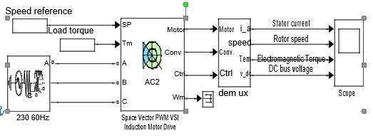
Figure 1: A model of the space vector PWM Induction motor drive system.
Appendix: Parameters of the Space-Vector PWM Induction Motor Drive
230 V, 60 Hz,1705 rev/min, 2.3 kVA cage induction motor:Stator: Resistance = 0.425 Ω, Leakage inductance = 2 mH.
Rotor:
Resistance = 0.820 Ω, Leakage inductance = 2 mH, Mutual inductance = 68 mH (all referred to the stator); Inertia = 0.086 kg/m2, Friction coefficient = 0.
Converters and DC link:
DC link capacitance = 3.4 mF.
Braking chopper:
Resistance = 58 Ω, Chopping frequency = 4 kHz, Activation voltage = 360V; Shutdown voltage = 325 V.
Rectifier:
Forward voltage of diode = 1.3 V, On-state diode resistance = 1 mΩ, Snubber resistance = 10 kΩ, Snubber capacitance = 0.02 µF.
Inverter:
Forward voltages of diode and IGBT = 1.2 V, On-state resistance = 1 mΩ; Turn-off characteristics: Fall time = 1µs, Tail time = 2µs; Snubber resistance = 500 Ω, and Snubber capacitance = 0.001 µF.
Controller and SVM generator:
Speed controller:
Speed ramp of acceleration/deceleration = ±1600 rev/min/s, Sampling time = 0.1ms, Volt/Hertz (VLL/f) ratio = 3.2, Zero speed crossing time = 0.4s, Sensor cut-off frequency = 100 Hz.
Output ranges: Controller [-30, 30], Frequency [0.05, 120] Hz, Voltage [10 180] V.
PI regulator gains: Proportional = 9, Integral = 10.
SVM generator:
Switching frequency = 4.2 kHz, DC link voltage sensor cut-off frequency = 50 Hz, Sampling time = 0.02 ms.
3-phase source:
230 V, 60 Hz, Internal resistance = 0.02 Ω, Internal inductance = 0.05 mH.


No comments:
Post a Comment